Carnegie Mellon University
The Sector Sweeper is a semi-autonomous discus retrieval bot, designed to pick up and store a track and field discus. There are currently no options available that allow for discus retrieval without having someone in the sector to pick up the discus, possibly putting them in harm’s way.
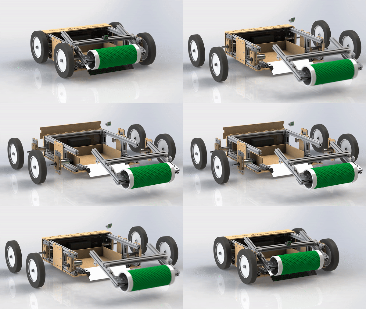
After a throw, a user will remotely drive the Sector Sweeper to the discus, at which point the autonomous mode takes over. The robot locates the discus using OpenCV and aligns itself to being collection. Once collected, the Sector Sweeper switches back to remote control mode, and the user can drive the robot back to the throwing circle.
As the collection subsystem lead, I was in charge of designing and building the combine harvester-like rotating drum on the front of the Sector Sweeper. This successfully pushes the discus up the small internal ramp and into the storage area. Due to the Coronavirus pandemic and the partially remote nature of the semester, I was also in charge of machining the bulk of our parts, as well as assembling the entire final product. I worked very closely with the movement and storage subsystem leads to adjust their CAD models and design the Sector Sweeper with manufacturability in mind.
This is an example of a full system test of the Sector Sweeper, taken from a video that I made to describe the process (which can be found here). The Sector Sweeper was voted “Best Overall Design” among my Electromechanical System Design capstone class, as well as “Best Design” out of all College of Engineering capstone projects across all majors at the Carnegie Mellon Design Expo.
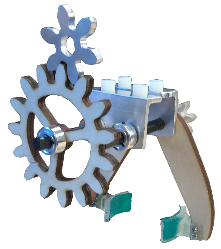
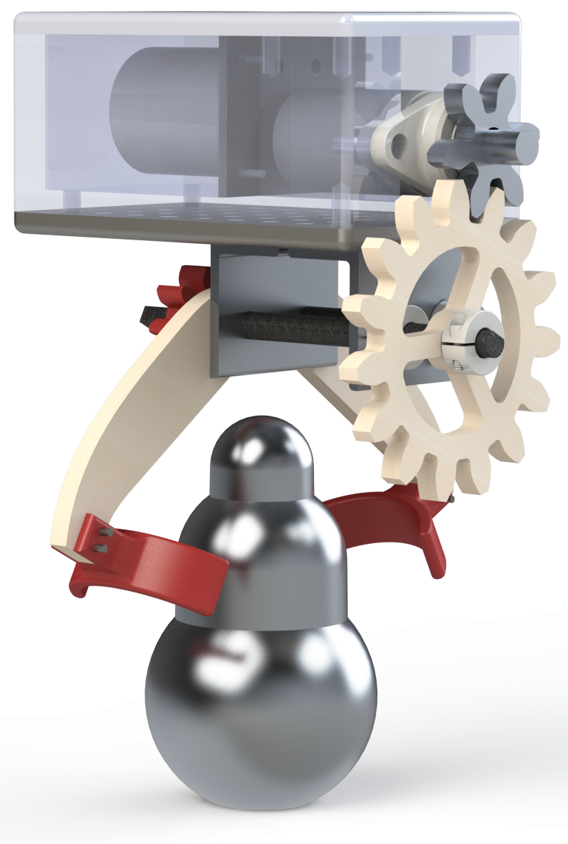
The dynamic swinging gripper has a fairly simple goal: grip the object and do not let it fall. The gripper attaches to the bottom of a mounting plate, and a motor must in some way activate the gripper to close around the artifact. Our gripper uses a two shaft design. The aluminum gear connects to the motor shaft, which in turn drives a gear that is fixed to one of the shafts. At the back of the gripper are 1:1 gears which ensure that the shafts turn simultaneously to grip the object.
This SolidWorks render is accurate to the final gripper used on testing day.
This is the second of our designs, coming in at 44% lighter than the design used on the first testing day. The white nylon pegs that are resting on the aluminum L brackets attach the gripper itself to the swinging arm.
The motor gear was chosen to be out of aluminum because our team encountered issues with shear at the keyed hole when we used a wooden motor gear. The fingers that grip the object are 3D printed using a Form 2, and have a thin layer of Dycem to increase the coefficient of friction. The arms and large tranmission gear are made out of durable 1/4” birch plywood. This is because plywood is lightweight, yet strong and ductile, allowing us some margin of error when the motor is stalling. The shafts are made out of 5/16” carbon rods that I machined to create square keys that hold the gears in place. We chose to use square keys instead of a D-shaft because it is less likely to wear out the interior of the gear and cause slippage.
This render shows how the gripper would grip around the artifact. Note that the fingers are not accurate to the gripper used on testing day. This is because we decided that the tips of the fingers did not offer us any advantage.
This is the crane project, shown here from above. The task was to design a crane that fit into a playing field without interference, maintained a certain level of rigidity while under a loading scenario, and was as light as possible. For loading, a 1 lb. weight was placed at the end of the crane, and the total deflection at the end had to be less than one inch.
We decided to go for a very minimalistic “open truss” look. This meant that while not being nearly as strong as a Warren truss, it is much lighter. We had to be very careful about bracing and supporting member placement - including precreasing some beams so that they fit the odd angles that would normally be solved with two or even three beams.
Here you can see our crane under the loading scenario of 1 lb. The total deflection was 3/4”. For the purposes of this project, if the crane deflects under 1” it is treated as a success - getting 1/4” deflection is just as good as getting 7/8”. Once we had the crane not deflecting at all, we began removing supports to get as close to the 1” limit with the lightest structure possible.
Our crane had just two arms - one that went through the window and one that went to the post. We decided to go for a singular junction point to save materials. The four beams of the major arm were bent into L shape cross sections to increase the moment of inertia. They were supported by a few cross braces and vertical braces throughout to keep their form.
In order for the members to come in at an angle and then meet flat, they were snipped. Because this is introducing a fissure, L supports were bolted to each member to hopefully regain some of the lost integrity.


