Dynamic gripper
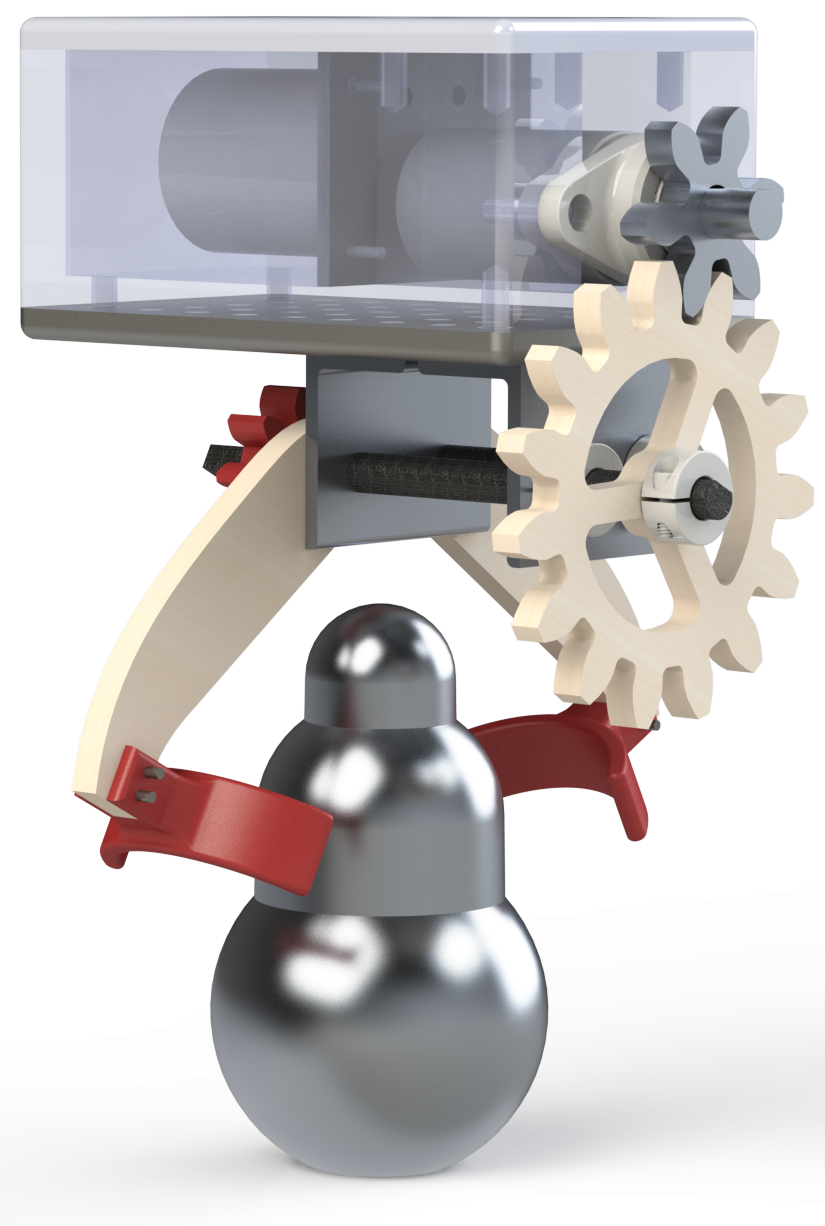
The dynamic swinging gripper has a fairly simple goal: grip the object and do not let it fall. The gripper attaches to the bottom of a mounting plate, and a motor must in some way activate the gripper to close around the artifact. Our gripper uses a two shaft design. The aluminum gear connects to the motor shaft, which in turn drives a gear that is fixed to one of the shafts. At the back of the gripper are 1:1 gears which ensure that the shafts turn simultaneously to grip the object.
This SolidWorks render is accurate to the final gripper used on testing day.

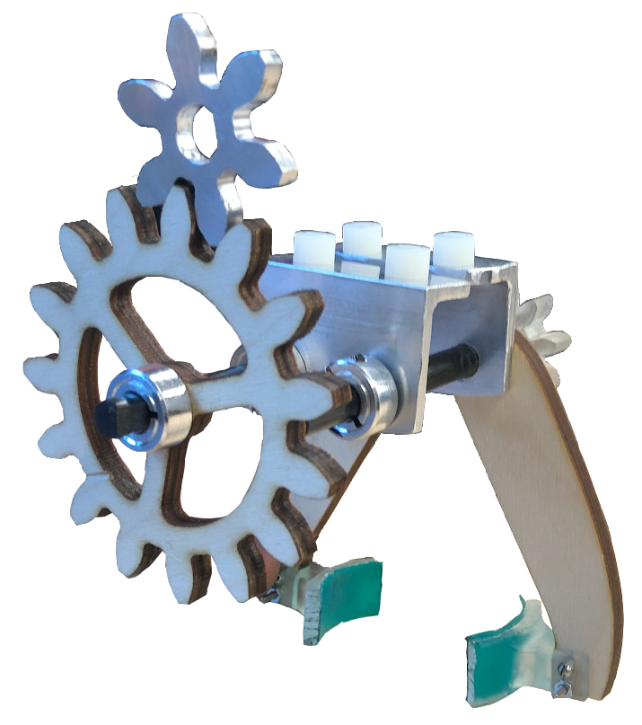
Test day gripper
This is the second of our designs, coming in at 44% lighter than the design used on the first testing day. The white nylon pegs that are resting on the aluminum L brackets attach the gripper itself to the swinging arm.

Material selection
The motor gear was chosen to be out of aluminum because our team encountered issues with shear at the keyed hole when we used a wooden motor gear. The fingers that grip the object are 3D printed using a Form 2, and have a thin layer of Dycem to increase the coefficient of friction. The arms and large tranmission gear are made out of durable 1/4” birch plywood. This is because plywood is lightweight, yet strong and ductile, allowing us some margin of error when the motor is stalling. The shafts are made out of 5/16” carbon rods that I machined to create square keys that hold the gears in place. We chose to use square keys instead of a D-shaft because it is less likely to wear out the interior of the gear and cause slippage.
This render shows how the gripper would grip around the artifact. Note that the fingers are not accurate to the gripper used on testing day. This is because we decided that the tips of the fingers did not offer us any advantage.


