Wheel fairing
The SolidWorks assembly of the final fairing design. It utilizes a low hatch angle to allow for lower coefficients of drag, as well as a rear upswept section to create a diffuser.

Side view of fairing
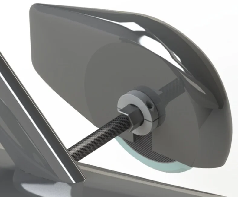
Here is a render of the new fairing attached to the CAD for a buggy. This was done to confirm clearances and geometry.

CFD on final fairing model
Here is a 3D computational fluid dynamics simulation on the model of the fairing. This was used to confirm higher conversion of dyanmic pressure into downforce.

Fairing on the buggy
Here is an initial prototype fairing on a buggy. It was fabricated with simple wet-layup techniques using Fibre Glast System 1000 resin and 3k twill weave. After attaching the two halves at the seam with strips of the same carbon fiber, it is filled with 8-lb pourfoam.
Note that this is using an older iteration of the fairings, and not the ones seen above. The above fairing was redesigned to reduce weight and improve aerodynamic efficiency.


